CS 6610 Advanced Computer Graphics - Project 3
Zach Gildersleeve
October 13, 2006
CADE login: gildersl
Graduate level credit
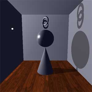 Fig. 1 - Projective Shadows |
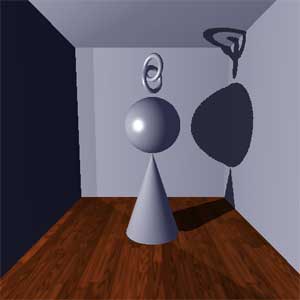 Fig. 2 - Depth Map Shadows |
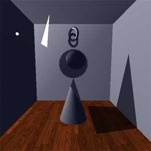 Fig. 3 - Shadow Volume |
Program Description
This program creates a cubical room, populated with a cone, a sphere, and two interlinked, rotating tori. A simple emissive sphere represents the diffuse light source that is available, in addition to a low level ambient light. The GUI allows the user to select between three shadow algorithms: projective shadows, depth map shadows, and shadow volumes. The user can also move the light position and change the light intensity, and for shadow volumes, scale the occluder geometry.
Source Code
The souce code, both the Xcode files and the Visual Studio files, can be found here (22.95MB .zip).
Development Platform
This project was coded in C++ in Xcode on OS X (10.4.7) and ported to MS Visual Studio 2005 on a Windows XP machine. This move was made to fulfill the assignment requirements.
Project Features and Design Choices
What follows is an in-depth description of the main program, and details of why certain design choices were made.
Upon launch, the program initializes the OpenGL state, establishes a dim, slightly blue ambient light and builds a diffuse positional light, and creates two texture objects. The floor texture is repeated from Assignment 2, and a second NULL texture is created that will store the depth map for when it is needed. The internal format for this texture is GL_DEPTH_COMPONENT, which isolates the required Z value for use in a depth map texture. This texture object is set up for future texture coordinate generation in eye coordinates, to dynamically map the shadows. Finally, these two texture objects are bound into texture units for multitexturing.
A white, emissive sphere is modeled where the light is positioned, and is constrained to remain within the room itself, but is not constrained to remain outside the sphere, cone, or tori geometry. The light and shadow behavior when the light in inside the sphere, etc. is undefined.
Projective Shadows
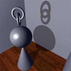
Fig. 4
As the glutMainLoop is entered, the scene defaults to projective shadows. As projective shadows can only cast onto planar objects, the room acts as receiver, and the cone, etc. act as the occluding objects. First, the room is drawn to the color, depth, and stencil buffers, with the stencil buffer set to 1 wherever the room is drawn. The stencil buffer is then set to draw only where it is equal to 1, and to increment upon zpass, which will avoid multiple layers of shadows in the final projective shadow. A loop is entered that will draw the shadows for the six sides of the room, "clipping" the shadows to the actual geometry via the stencil buffer. To draw a projective shadow on a single plane, a plane equation in the format Ax + By + Cz = D is created that matches the planar surface (floor, walls, etc.), and an appropriate shadow matrix is generated that flattens the Modelview matrix onto that plane. This flattened geometry is then drawn, without lighting, which with the appropriate blending produces a planar projective shadow that is lit by the ambient light. NOTE: A step in the standard projective shadow algorithm calls for polygon offset, to avoid Z-fighting between the geometry and the projected shadows. This is excluded here, though, because we know the size of the room, and can manually offset the shadows (by a value of 0.1), which saves several changes to the OpenGL state. As there is an ambient component to the diffuse positional light, that is, we would expect the ambient light level to increase as the diffuse light level increases, the shadow is "modulated" by the ambient term in the blend function. The result are crisp shadows that are cast on the planar surfaces of the room, but do not extend beyond the actual drawn geometry, as show Fig. 4. As each planar surface receives a shadow, there is no problems created by the "look at" position of the light. This does become a problem with depth map shadows, as we will see.
Depth Map Shadows
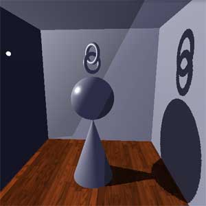 Fig. 5 |
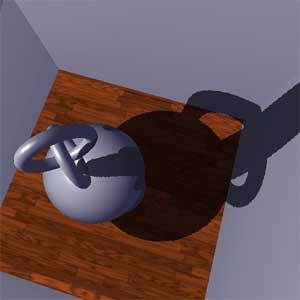 Fig. 6 |
The user can select depth map shadows via the GUI. This implementation of depth map shadows provides a good idea of the positive and negative aspects of depth map shadows. First, the depth map is rendered from the light's POV, and stored in the GL_DEPTH_COMPONENT texture object. This is done by making the necessary changes to the Projection and Modelview matrix via the associated gluPerspective() and glLookAt()/glViewport() calls. The depth buffer is drawn, with all unnecessary state disabled (like lighting), and then copied into the texture unit. Here, polygon offset is used, as that forms the basis of the necessary bias in the shadow map algorithm. The identity matrix is loaded on the texture stack, and the scale, bias, and multiplications necessary to translate the depth map from the light's POV to the eye's POV are performed here. This does require more calls than the Red Book example of depth map shadows, which operates on the model view stack, but with the inclusion of multitexturing and texture units to texture the floor, proves to be more straightforward. The Projection and Modelview matrixes are returned to the camera controls. A two step rendering is done to draw the shadows. First, a low level light is used to draw the entire scene, this is meant to simulate the effects of ambient light. Then, texture coordinates are generated in eye space and using the alpha test, fragments from the eye's POV are determined to be lit or in shadow. Finally, all fragments that are determined to not be in shadow are redrawn, which results in a shadowed scene.
Figure 5 illustrates the scene with depth map shadows, and illustrates several of the key limitations of this method. While there is a nice level of self-shadowing (see Fig. 6), the shadows are limited by where the light looks at. In this scene, anything from the light's POV is taken to look at the origin, which is at the center of the sphere. Due to this, at some light angles, the cone's shadow does not extend to the cone base, or similarly for the tori. Also, as a more robust depth map shadow method calls for a cubical projection of the shadows onto the scene, here only the front facing plane is projected from the light, which exaggerates the above problem, and also draws artifacts behind the light in the form of the shadow texture. A clipping plane attempts to fix this problem, but the clipping plane's effectiveness is tied into the scene size and camera position, and had different behavior on the Mac OS X development versus MS Visual Studio. Further, the aliasing associated with depth map shadows is clearly visible.
Shadow Volumes
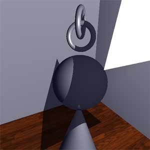 Fig. 7 |
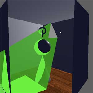 Fig. 8 |
As the user selects shadow volumes, a simple triangle shaped occluder is drawn. A complicated first step in the shadow volume algorithm is the identification of the geometry silhouette edges from the light's POV, however, as we are only interested with the triangle occluder casting shadows, the triangle's position is hard coded in the program. After the visible triangle is drawn, the triangle's vertices are extruded to a value set as "infinity," here that value is 200.0. A number smaller than 20.0 focuses the volume to a point within the room, and as the extruded points move away from the light to infinity, the extruded edges grow parallel. From these extruded points, the shadow volume is drawn and capped on both ends in the stencil buffer only (Fig. 8). An ambient pass of the geometry is drawn, for the same purpose as the depth map shadows. The shadow volume method follows the zpass algorithm, in that first the front facing only geometry of the shadow volume is drawn, and the stencil buffer incremented where a fragment passes the z test (from the eye's POV), then the same geometry is drawn, but this time only back facing faces, and the stencil buffer is decremented where the z test passes. The result is the stencil buffer populated with a 0 where fragments are lit, and some other value where they are in shadow, and the geometry is drawn again to produce the shadowed image.
Graphical User Interface
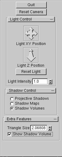 |
A GUI implemented in GLUI provides additional features. The Quit button exits the program, and the ResetCamera button resets the camera to its default position, at (0.0, 0.0, -40.0) looking at the origin. In the Light Control, the light map position can be controlled by the two GLUI position widget, one which controls the XY position, and one that controls the Z position. A reset light button returns the light to it's original position, and the light's diffuse intensity can be controlled with the spinner. As there is an ambient quality to the diffuse light, as the light's intensity is increased, the overall light levels (as indicated in the shadows) increases as well. The method for generating shadows can be selected via the radio button group. When the shadow volume button is selected, the triangle occluder is drawn. It is important to note that from some light positions the triangle will not cast a meaningful shadow, and the light must be moved into position as required. The shadow volume implementation also allows some additional features, found in the "Extra Features" rollout. The triangle size can be increased using the spinner, and the shadow volume geometry can be made visible if desired. |
Known Bugs and Issues
- As noted above with the depth map shadows, there are several visible issues with shadow maps in general, that manifest themselves in various ways. Behind the light, the shadow map image is duplicated. This would not be an issue with a cube map implementation of the depth map. Also, as the depth map is always centered at the light's lookat point (the center of the sphere) sometimes what is shadowed and what is lit is less than intuitive. Finally, at certain light angles relative to certain camera positions, the shadow's become completely solid, rather than lit by the ambient light. This behavior seems to grow worse as the light approaches the sphere geometry, with the shadows becoming undefined as they enter the sphere's geometry, and tends to vary across platforms. It is difficult to identify what are vaild concerns, and what are typical artifacts encountered from implementations of shadow maps.
- The shadow volume is not robust to the extend that the shadows draw properly when the camera is inside the shadow volume itself. There is a visible shift as the camera passes through the shadow volume geometry, and the shadowed geometry becomes simply shaded. Likewise, at certain camera positions relative to certain light positions, the shadows as they extend onto the tori do not shadow correctly, although this behavior exists only at the linked section, and each torus individually shadows normally.